I picked up my Arduino learning kit from Jaycar earlier today. I wasn’t in class for the intro on Arduino or anything so I have some catching up to do!
Reading the quick start booklet and following along with youtube videos were my best friend. Here are a couple of videos I watched:
Button LED video
Button LED video 2
Arduino Intro
I began with the very first example in the booklet which made the onboard LED blink on my UNO by loading up a simple example.
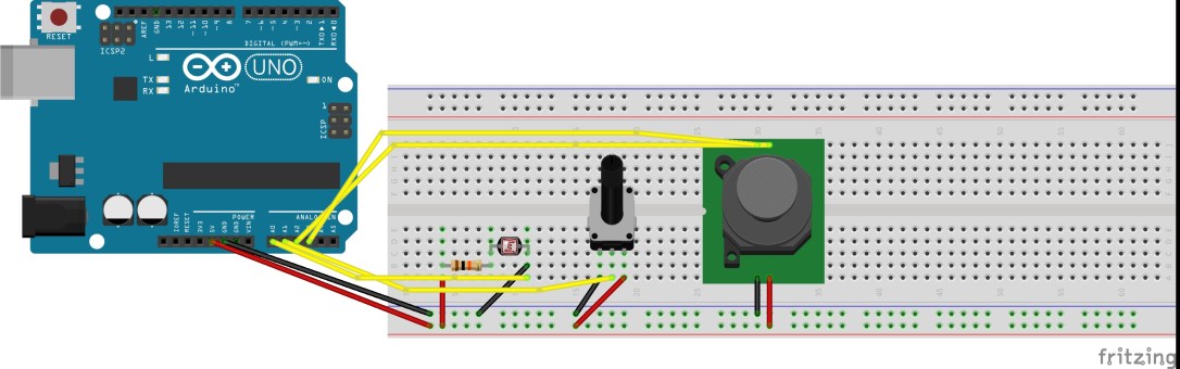
After that I tried to incorporate an external LED to turn on by a button press which I managed to do. A link to my Instagram post showing it. Loading up the ‘Button’ example in the Arduino IDE, then following a little diagram and some youtube videos to connect the board up correctly.
Barely scratched the surface of whats possible with this thing and looking forward to learning much more of what its capable of.
The coding was as follows…
/*
 Button

Turns on and off a light emitting diode(LED) connected to digital pin 13,
 when pressing a pushbutton attached to pin 2.

The circuit:
 - LED attached from pin 13 to ground
 - pushbutton attached to pin 2 from +5V
 - 10K resistor attached to pin 2 from ground

- Note: on most Arduinos there is already an LED on the board
 attached to pin 13.

created 2005
 by DojoDave <http://www.0j0.org>
 modified 30 Aug 2011
 by Tom Igoe

This example code is in the public domain.

http://www.arduino.cc/en/Tutorial/Button
*/

// constants won't change. They're used here to set pin numbers:
const int buttonPin = 2; // the number of the pushbutton pin
const int ledPin = 13; // the number of the LED pin

// variables will change:
int buttonState = 0; // variable for reading the pushbutton status

void setup() {
 // initialize the LED pin as an output:
 pinMode(ledPin, OUTPUT);
 // initialize the pushbutton pin as an input:
 pinMode(buttonPin, INPUT);
}

void loop() {
 // read the state of the pushbutton value:
 buttonState = digitalRead(buttonPin);

// check if the pushbutton is pressed. If it is, the buttonState is HIGH:
 if (buttonState == HIGH) {
 // turn LED on:
 digitalWrite(ledPin, HIGH);
 } else {
 // turn LED off:
 digitalWrite(ledPin, LOW);
 }
}