For this project I basically expanded off my most recent blog post which you can read here.
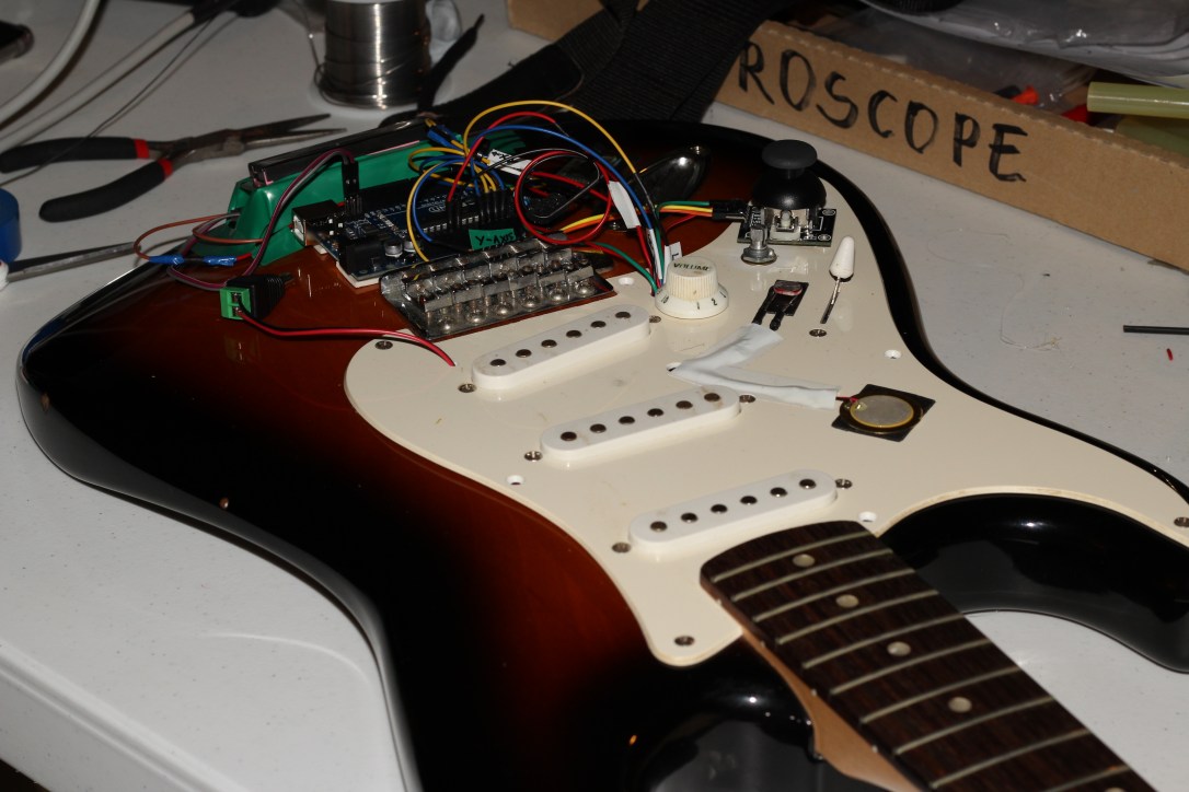
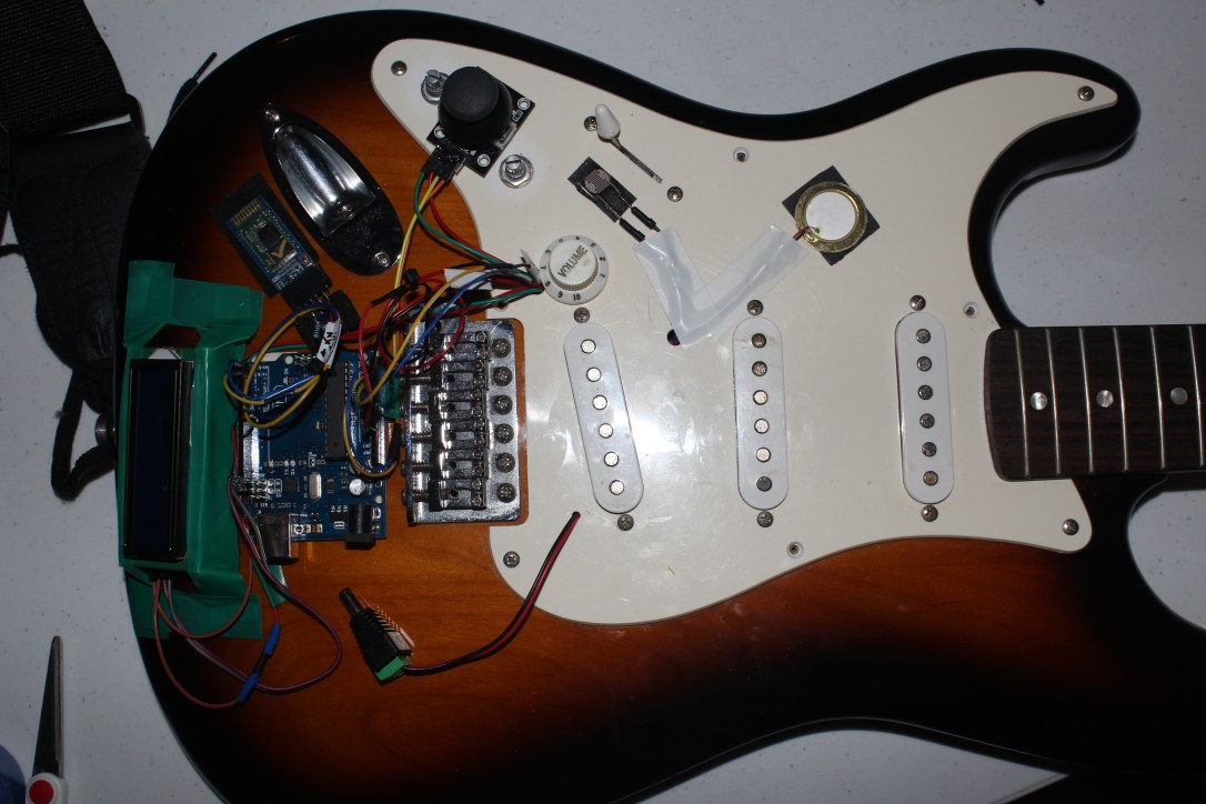
In this project my end goal was to have five sensory inputs hooked up to my Arduino Uno that would be used to control values inside a Max patch which includes synthesis and visual display/feedback.
My inputs included
- Light Dependent Resistor (LDR)
- Rotary potentiometer
- Joystick
- Trim Potentiometer
- Push button
The final product and tutorial can be seen here – Youtube Demonstration
Arduino Patching
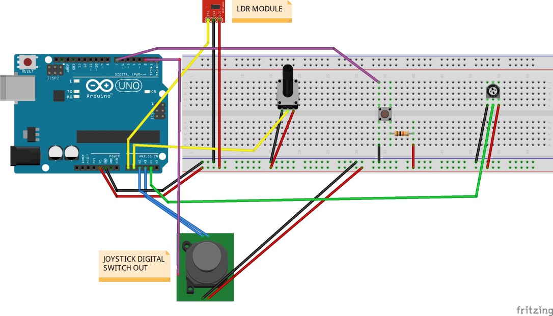
I have provided a circuit diagram created in the program Fritzing. which displays how I wired everything up.
Arduino Sketch IDE
I based the foundation of my sketch around the ‘virtual color mixer’ example sketch within inside Arduino IDE. Re-labelled some code so they matched my components and also added four new fields to allow for my other inputs, because virtual color mixer is based off 3 analog ins to control RGB fields. That involved adding ‘const int’ lines at the start of my code then referencing to them in my void loop using ‘serial.print(());’ .
Another factor to take into account was to add the extra code needed for the digital inputs incorporated. Virtual Color Mixer’s code is only setup for 3 analog ins. Looking at examples for the use of a button, I worked out how to combine the button code into my project. Here is my modified sketch…
const int LDR = A0; // Light dependent resistor
const int Potentiometer = A1; // rotary potentiometer
const int JoystickX = A2; // joystick x axis
const int JoystickY = A3; // joystick y axis
const int JoystickBut = 2; // joystick button
const int Potentiometer2 = A4; // potentiometer (screwdriver)
const int buttonPin = 7; // pushbutton

int buttonState = 0;

void setup() {
 Serial.begin(9600);
 pinMode(buttonPin, INPUT_PULLUP);
 pinMode(JoystickBut, INPUT_PULLUP);

}

void loop() {
 buttonState = digitalRead(buttonPin);

 Serial.print(analogRead(LDR));
 Serial.print(",");
 Serial.print(analogRead(Potentiometer));
 Serial.print(",");
 Serial.print(analogRead(JoystickX));
 Serial.print(",");
 Serial.print(analogRead(Potentiometer2));
 Serial.print(",");
 Serial.print(digitalRead(buttonPin));
 Serial.print(",");
 Serial.print(analogRead(JoystickY));
 Serial.print(",");
 Serial.print(digitalRead(JoystickBut));
 Serial.println(",");


}
Once you upload that onto your Arduino board you are ready to open up Max.
Max Patch
The same concept applied here in the sense that I brought over the Max code included in the Virtual Colour Mixer example in the IDE. All that was required in order for Max to see my inputs’ values was to add extra ‘0’ fields into my unpack object. The way the code was done in Arduino, every second output on the unpack object is a feed of analog data. For example if I were to have 3 inputs, I would then need 6 zeros entered in my unpack.
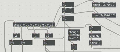
When you open up my Max patch you will see the values of my inputs entering Max are then feeding different oscillators frequencies and controlling parameters for my jit objects. For some inputs I have divided or multiplied their values to make them more or less drastic. One object I found super useful was ‘zmap’. This allowed me to specify a range for me inputs to fall between. For example most attributes for my jit matrix would only work nicely in small values (0 to 3). So I would use zmap to tell it to scale values from 0 to 1024 down to 0 to 3.
The next thing I wanted was for my buttons (push button and joystick switch) to latch down when pressed. By default the button only sends out a 1 forever how long it is held down. In order for this to be changed I took the output of my button value into a ‘change’ object then into a ‘select’ object with a value of 1. This gave me the result I was after.
Audio
All sound from this patch is the accumulation of 4 oscillators…
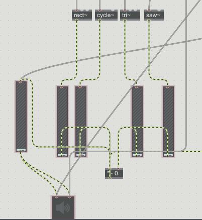
The LDR, Potentiometer and Joystick (x and y) are constantly feeding the oscillators with a frequency to produce. Each input is responsible for a separate oscillator. Then the little trim potentiometer is mapped to the master volume for the synths.
That is pretty much it in terms of the audio processing for this patch.
Visuals
I based the majority of my visual work off a youtube tutorial I watched on Jitter. Which can be seen here – Link to tutorial
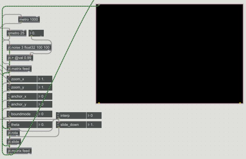
Basically all the visuals are is a jit.noise object that uses jit.feedback on itself. Plus a whole bunch of attributes to manipulate the imagery further. A handful of these attributes such as the zoom, theta, slide_down etc. are being controlled by my sensory inputs so they affect the audio and the visuals inside of Max.
The beauty of this patch is that once you have your Arduino communicating properly with Max and you are seeing your inputs values you can route them to control basically anything inside of Max. The possibilities are endless in other words.
That pretty much covers the whole design in detail, see it come to life HERE