
I followed the example ‘VirutalColorMixer’ under the communications tab in Arduino to begin this project. Here is a diagram I created of my design using the program Fritzing:
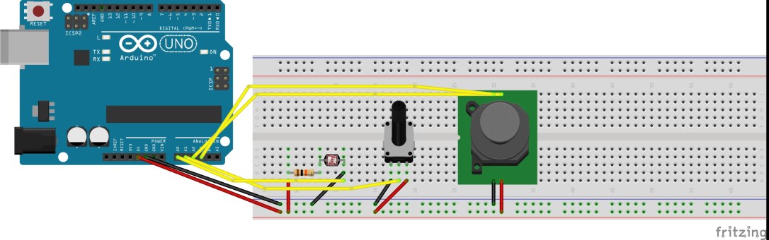
I only had one LDR module so I used a rotary potentiometer and a joystick for the rest of the analogue inputs required to control the red, green and blue fields.
After I hooked up my circuit, I uploaded the VirtualColorMixer to my Arduino board then opened up Max 7 and copied over the example but for the Max patcher. I then used the values from each of my analogue inputs to feed a certain oscillator a frequency value. The rest was as follows…
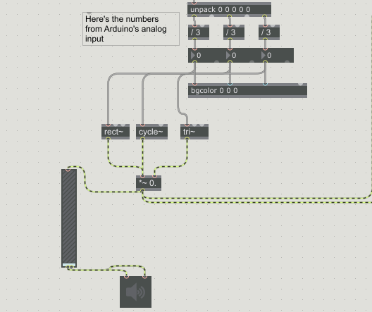
Here is what the end result ended up looking/sounding like – Link to Video
Not seen in the video above but the input values control the background colour of the Max patch (what the patch is originally meant to do).
Doing this little project helped me get an understanding of how to integrate the Arduino board into Max and also more experience in planning and constructing a circuit.
Excited to make more projects with this thing in the future!
